5. Algorithm
5.1. Overview
A list of algorithms is implemented to carry out the following operations:
Flowline simplification
Mesh generation
Topological relationship reconstruction
5.2. Flowline simplification
5.2.1. Dam associate flowline burning
(Optional)
Through a look-up table that links dams with their associated flowlines, this algorithm includes all the downstream flowlines of each dam into the flowline simplification process.
Currently, this algorithm does not include the upstream of a dam.
5.2.2. Flowline vertex extraction
The vertices that make up flowlines are used in several algorithms. Among them, a flowline’s starting and ending vertices also define the flowline type.
If the starting vertex has no upstream, the flowline is a headwater.
If the starting or ending vertex has only one upstream or downstream, it is a middle flowline and can be merged with others.
If a starting vertex has more than one upstream vertices, it is a river confluence.
5.2.3. Split flowline
With all the flowlines and vertices, the algorithm split the flowlines into a minimal set that meets the following requirement:
All flowlines’ starting and ending vertices are made up by the vertex loop-up table.
No flowline has a middle vertex that belongs to the same look-up table.
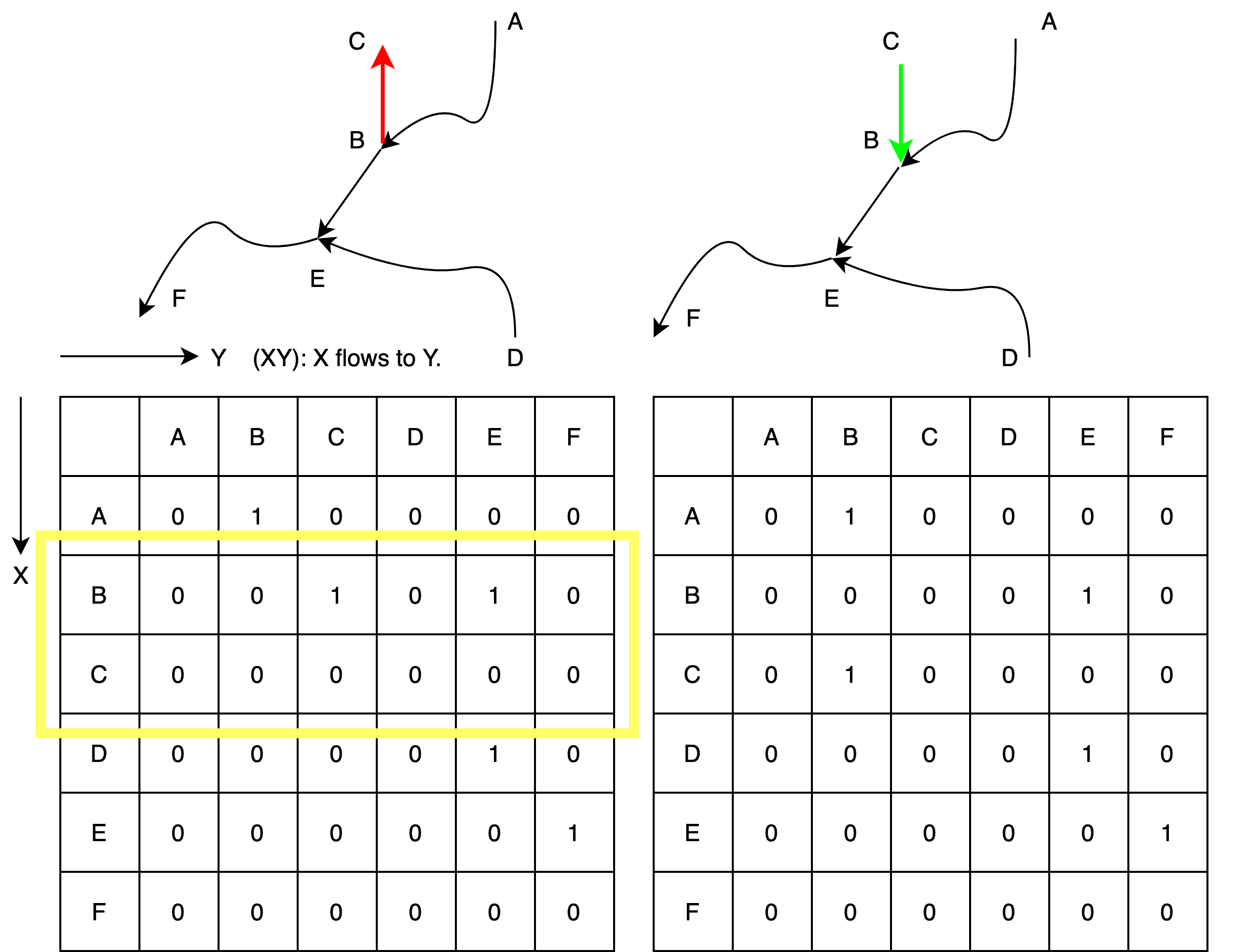
5.2.4. Flow direction correction
Due to data quality issues, the existing flowlines may have incorrect flow directions, which lead to multiple downstream flow directions. The corresponding node connection matrix has rows with multiple *1*s. This algorithm scans from the outlet vertex and searches reversely; once such a row is detected, the corresponding flow direction is reversed.
5.2.5. Remove small river
To simplify the river networks, small rivers with lengths less than the user-provided threshold are removed. This algorithm only applies to headwater and should be called multiple times to achieve desired performance.
(Optional) When the dam burning is turned on, the dam-associated flowlines are always retained even if their lengths are less than the user-provided threshold.
5.2.6. Remove braided flowlines
A braided loop occurs when a vertex has more than one downstream, even after the flow direction correction. This algorithm removes these loops by only keeping the first detected downstream of any vertex.
5.2.7. Flowline confluence extraction
This algorithm scans the whole network and defines the vertices that have more than one upstream flowline as river confluences.
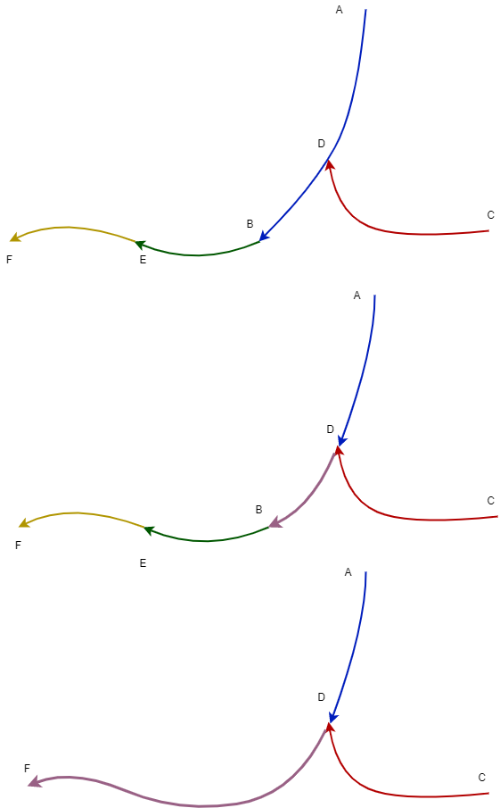
5.2.8. Merge flowline
This algorithm merges flowlines, so there are only two types of flowlines:
headwaters
flowline between the confluences
If there are multiple flowlines within the same confluence bound, they are merged as one.
5.2.9. Flowline confluence definition
After the flowlines are in the final format, the confluences are redefined using the same criteria as above.
5.2.10. Stream segment index
This algorithm defines the stream segment index using their topologic relationship..
5.2.11. Stream segment order
This algorithm defines the stream order based on the stream segment topology and the classic stream order, also called Hack’s stream order or Gravelius’ stream order method.
5.2.12. Split flowline by length
(Optional)
In some cases, it is desirable to impose a maximum flowline edge length so it can be used in other applications. This algorithm divides such kinds of edges until they meet the requirement.
5.3. Mesh generation
PyFlowline provides several algorithms to generate structured meshes, including latitude-longitude, projected, hexagon, triangle meshes.
The hexagon mesh generator also provides an option for a 60-degree rotation (https://www.redblobgames.com/grids/hexagons/#basics).
PyFlowline uses the geographic coordinate system (GCS) exclusively for all the computational geometry, all the meshes are converted to the GCS system. See the hexagon mesh for an example.
5.3.1. Structured mesh
In general, the mesh generator creates mesh cells one by one in a pre-defined row-column order starting from the lower left corner. The generator calculates the locations of all vertices of each mesh cell. The coordinates will be converted back to GCS if the mesh is in PCS.
Usually, the domain’s boundary is defined in the configuration file, and the algorithm starts from the lower left.
5.3.1.1. Latitude-longitude mesh
Coordinates of 4 vertices are calculated, then a cell is defined.
Repeat until all cells are generated
5.3.1.2. Projected mesh
Coordinates of 4 vertices are calculated and re-projected to GCS, then a cell is defined.
Repeat until all cells are generated
5.3.1.3. Hexagon mesh
Coordinates of 6 vertices are calculated and re-projected to GCS, then a cell is defined.
Repeat until all cells are generated
5.3.1.4. Triangle mesh
Coordinates of 3 vertices are calculated and re-projected to GCS, then a cell is defined.
Repeat until all cells are generated
5.3.2. Unstructured mesh
PyFlowline does not provide unstructured mesh generations. Instead, the user should use third-party generators such as the JIGSAW to generate the mesh files. PyFlowline only provides algorithms to import these mesh files and convert them to PyFlowline-supported mesh data type.
5.3.2.1. MPAS
Supported by JIGSAW
5.3.2.2. TIN
Not yet supported
5.3.2.3. DGGrid
Not yet supported
5.4. Topological relationship reconstruction
5.4.1. Mesh and flowline intersection
This algorithm calls the GDAL (https://gdal.org/) APIs to intersect the mesh with the simplified river network. Each stream segment is broken into reaches.
5.4.2. Topological relationship reconstruction
After the intersection, this algorithm rebuilds the topologic relationship using the entrance and exit vertices of each reach to construct the reach-based or cell center-based river network.
5.4.3. Remove returning flowline
This algorithm simplifies the topology information for several unusual scenarios. For example, if a flowline leaves and reenters the same mesh cell through the same edge, this creates a loop in topology and will be simplified.